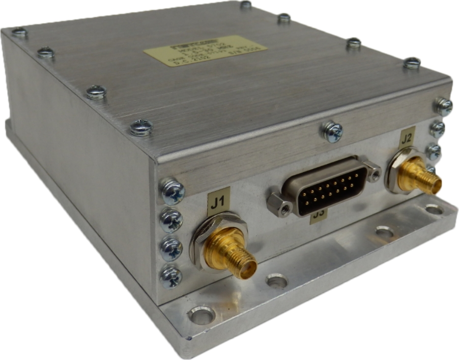
5702
Netcom’s 5702 is a tunable filter covering the frequency range of 1.5MHz to 30MHz.
This 1.5-30MHz LRU filter has been designed using three bands of tunable filters. This tri-band filter is offered in a mechanical package to support applications where compact design, power requirements, and mechanical installation flexibility are important. It meets the vibration and shock requirements of systems used in ground-mobile and airborne environments.
- Specifications
- Performance
- Mechanical
- Serial Address
- More Details
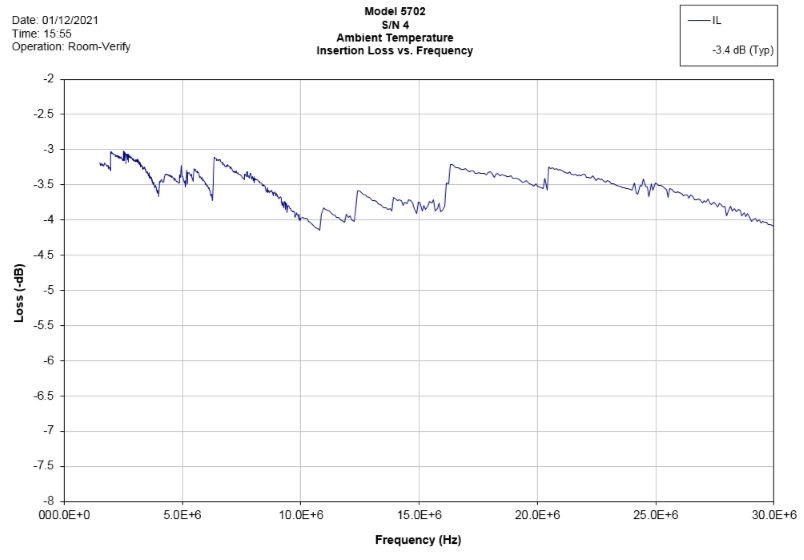
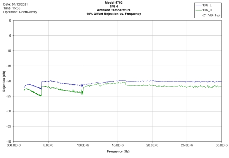
The following table shows the typical performance of the filter at a bandwidth of 5.3%. Options are available upon request for different bandwidths.
| Frequency Range | 1.5 to 30 MHz | ||
| BW (Typical) | 5.3% | ||
| Impedance (Input /Output) – Typical | 50 Ω | ||
| Fc + 10% Selectivity – Typical | < -19dBc | ||
| 2Fc | < -60dBc | ||
| Tuning Speed | < 200 µs | ||
| Insertion Loss Typical | 3.5 dB | ||
| Insertion Loss Max | 4.5 dB | ||
| Return Loss Min | 8.5 dB | ||
| Tuning Channels | |||
| 1.5MHz- 4MHz | 250 | ||
| 4.0MHz– 10MHz | 249 | ||
| 10MHz– 30MHz | 249 | ||
| RF Input Power (P1dB) | |||
| 1.5MHz to 4MHz | 20dBm | ||
| 4MHz to 10MHz | 27dBm | ||
| 10MHz to 30MHz | 28dBm | ||
| In Band Power Handing Max | 30dBm | ||
| Out of Band Power Handing | 33dBm | ||
| IP3 | |||
| 1.5MHz to 4MHz | 31dBm | ||
| 4MHz to 10MHz | 38dBm | ||
| 10MHz to 30MHz | 39dBm | ||
| Vcc Range | 6.0V to 15.0V | ||
| DC Current Max | 275mA | ||
| Operating Temperature Range | -40 to +85°C | ||
| Control Interface | SPI Interface | ||
| Dimensions [L x W x H] | 5.50 x 4.00 x 1.966 inches 139.70 x 101.60 x 49.92 mm |
||
Insertion Loss
10% Rejection
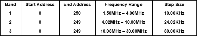
Band Switch Table
| Band | B1 | B0 | Frequency Range |
| 1 | 0 | 0 | 1.50MHz – 4.00MHz |
| 2 | 0 | 1 | 4.02MHz – 10.00MHz |
| 3 | 1 | 0 | 10.08MHz – 30.00MHz |
| Illegal Selection | 1 | 1 | Do Not Select |
Address Table

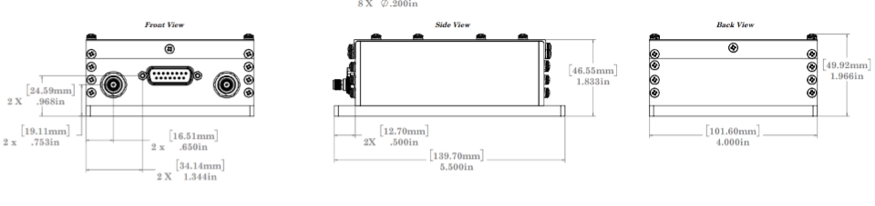
Connector Pin Out (DB15 Male)
| PIN DESIGNATORS | |
| PIN NUMBER | DESCRIPTION |
| 1 | TUNE_READY |
| 2 | NC |
| 3 | NC |
| 4 | NC |
| 5 | NC |
| 6 | NC |
| 7 | GND |
| 8 | VCC (6V to 15V) |
| 9 | GND |
| 10 | NC |
| 11 | GND |
| 12 | GND |
| 13 | SPI_CS |
| 14 | SPI_SCLK |
| 15 | SPI_MOSI |
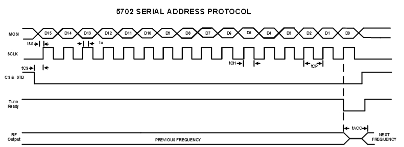
Serial Address Input Timing Diagram
When the SPI_CS line is shifted low, the Tune_Ready line will go high indicating the unit is ready to accept the tune word. Tuning of the filter starts when the last data clock (16th) pulse of the address is sent to the unit while the SPI_CS (Chip Select) is low. While the filter is processing the tune word request, The Tune_Ready Line will be low. When the filter tuning is complete the Tune_Ready line will go high to indicate the filter tuning is complete. Reset the SPI_CS line high after sending the 16th clock bit to allow the unit to reset after the filter tuning is complete.
Note: Monitoring of Tune_Ready line is not required.
| Symbol | Parameter | Min | Max | Units |
| tSS | Setup time MOSI Data to SPICLK | 50 | ns | |
| tu | Hold Time MOSI Data From SPICLK | 0 | ns | |
| tCH Clock High Time | 125 | ns | ||
| tCP | Clock Period | 250 | ns | |
| tCS | Chip Setup Time (CS falling edge to SPICLK start) | 125 | ns | |
| tTR | Tune_Ready indicator | 200 | us | |
| tACC | Access time from Last (16th) SPICLK edge to Fo | 200 | us | |
| Maximum Hop Rate Tune Frequency to next Tuned Frequency | 500 | Hz |
Bit Map

Environmental Specification Standards
Temperature:
- High temperature shall meet MIL-STD-810E, Method 501.3, Procedure I to 85°C storage, and procedure II to 85°C operating.
- Low temperature shall meet Method 502.3, Procedure I to -57°C storage, and Procedure II to -40°C operating.
Vibration:
- MIL-STD-810E Method 514.4 Ground Mobile Test Procedure I, Test Condition I – 3.4.7
Shock:
- MIL-STD-810E Procedure I, Method 516.4 – Functional Shock.
Reflow:
- None
MSL (Moisture Sensitivity Level):
- Level 0