
Co-Location Interference Mitigation; otherwise known as Cosite Mitigation
As the number of voice and data wireless applications increase in the commercial and military industries, the number of radio transceivers are increasing and transmitting at higher output power. In most cases, these newly deployed transceivers must operate in the same radio band and use antennas that are in close proximity to other transceivers. These situations, where multiple radios are in close proximity to each other, are referred to as co-located (cosite) radios.
Defining Interference and Cosite Mitigation
Cosite transceivers create an increased level of system self-interference. Most transceiver systems designed to solve cosite interference, rely on simple receiver pre-selection and do not adequately address cosite self -interference issues. Additionally, newer deployed transceivers use low power band pass filtering before the transmitter power amplifier to reduce the undesired spectral content of the exciter. These methods are proving to be inadequate for today’s radio networks.
Radio Networks with a Limited Number of Transceivers
Radio networks that only use two cosite transceivers use a more traditional solution (Figure 1) with a receiver pre-selector (grid pattern in the figure below) to remove the neighboring transmitter signal from the receiver input. In some cases there is a low-power filter (dot pattern in the figure below) in the nearby transmitter to reduce the sideband interference. In essence, both filters are used to prevent the one transceiver’s transmit signal from interfering with the other transceiver’s ability to receive a desired remote signal.
Figure 1 – Filtering Needed for a Small Number of Transceivers
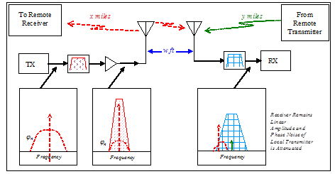
This method is only effective when there are two radios co-located in a radio network. It does not solve interference problems due to multiple (more than 2) cosite transceivers that are located in the same radio network. When multiple radios are closely located and transmitting simultaneously, they interact with each other and produce transmitter-to-transmitter inter-modulation distortion products – commonly referred to as reverse inter-modulation products or “IMPs”.
Reverse Intermodulation Distortion
In contrast to the situation shown above, two or more active transmitters that are closely located result in additional interference products because their signals mix in the output stages of each transmitter. This is illustrated in the diagram below (Figure 2).
Figure 2 – Reverse Inter-Modulation Products (IMPs) Interference
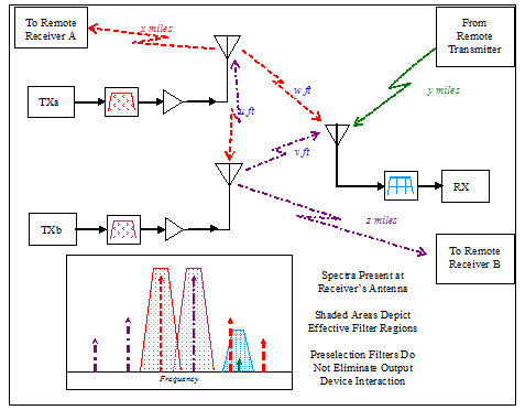
This diagram shows two transmitters that use filtering before the power amplifier (dot pattern in the diagram above) and a receiver that uses a pre-selector (grid pattern in the diagram above). The receiver’s pre-selector filter sufficiently attenuates direct transmitter interference. However, the transmitter produced IMPs (3rd and 5th order shown in the bottom of the diagram) that have the ability to desensitize the receiver. A 3rd order IMP (red signal in the diagram above) is discovered in the pre-selector pass band and is interfering with the desired receive signal (green signal in the diagram above).
Problems with Inter-Modulation Products
An IMP can desensitize a receiver in various ways. First, if the IMP is large enough to interfere with the receiver’s front end, it can reduce the receiver gain directly by driving down the AGC (Automatic Gain Control). Second, if the interfering signal is within the pass band of the pre-selector, but outside the IF filtering, saturation of receiver input will occur. This creates another issue, as saturation also limits the effective gain at the desired frequency blocking reception. Third, a less obvious problem that can occur is reciprocal mixing in the receiver. Reciprocal mixing occurs when an interfering signal is present at the first receive mixer, at a level where the phase noise of the internal local oscillator mixed with the interfering signal, and swamps the desired signal. This can occur when the interfering signal is outside the IF band and without saturating the receiver input. The internal factors that contribute to this phenomenon are the phase noise of the local oscillator and IF bandwidth. Reciprocal mixing artificially degrades the receiver noise figure. Due to these three factors the IMPs must be attenuated at their source.
The following contributing factors to IMP distortion can be used to determine if reverse IMPS cause significant interference problems:
1. Frequency Management – Spectral separation between communication networks allows normal pre-selection filtering to protect the receiver input from overload. This management is much more difficult in frequency agile (frequency hopping) systems that use the same communication spectrum.
2. Isolation between Transmitters – As the physical separation between the transmit antennas are reduced, more energy transfers between the co-located transmitters. This energy mixes with the signals transmit signals in each of transmitter and creates IMPs that radiate from each respective antenna.
3. Transmitter-to-Receiver Isolation – Location of the receive antenna relative to a nearby transmitter antennae determines the level of interfering energy radiated into the receiver.
4. Transmitter Power – Higher transmit output power affects IMP power in the same way as the physical separation of the transmit antennas. (Unfortunately, solving this issue by lowering the transmit power also reduces the communication range of the radio networks).
5. Transmitter Output Section Linearity – The transmitter power amplifier (PA) bias class can strongly affect the amplitude of the IMPs. As the PA bias changes from C class to B class to A class, the amplifier will operate more linearly. If the amplifier is biased in the linear region, it reduces mixing caused by nonlinearities inherent to high power devices.
A first order approximation of the IMP performance of a system can be predicted by the formula for unbalanced power inter-modulation distortion.
Some solutions that have been deployed use:
• High antenna isolation
• Time sharing and frequency planning
Today’s radio network trend is to continue to group many transceiver antennae together to maintain continuous use of the communication network, while employing the use of frequency agile systems. As a result of this radio network evolution, a new solution is required to reduce cosite interference.
The Solution
To solve this problem, a state-of-the-art transmit PA post-selector filtering solution for co-located radio networks. Such Cosite Filtering Amplifiers are deployed today, as an Integrated Filter Power Amplifier (IFPA) for military communications. This high power switching filter amplifier controls all aspects of cosite interference (cosite mitigation), by adding a transmit PA post-selector filter (shown in Figure 3) to reduce the IMPs. This proven technology was designed for low distortion, effectively removing the reverse signals applied to the transmitter power amplifier and the IMPs produced in the power amplifier.
Figure 3 – Improved IMPs with Post-Selector Filters
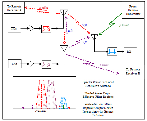
IMPs can be attenuated significantly by the selectivity of the filter. In an ideal case, if the filter has 25dB attenuation at 10% offset and the transmitters are separated by 10% in frequency, then using formula (1), the 3rd order IMPs in previous example is pulled down to -75dBm at the receiver input versus -25dBm without using a post selection filter.
Although the high-level system design is presented above, the solution has proven to meet low loss, high power and fast switching requirements for frequency agile systems.
Using a Cosite Filtering Amplifier provides a Cosite Mitigation solution for You
The Cosite Filtering Amplifier offers a transmit/receive switch, a power amplifier, and a frequency agile filter for both pre and post frequency selection. The advantage to this solution is that most or all channels are free from interference. In addition, less frequency planning is required for the radio network. The technology allows the use of multiple co-located transceivers, while reducing the deployment costs for new and evolving wireless communication applications. – Warren Guthrie
For more information please contact Netcom at [email protected] or visit their website at www.netcominc.com.